
Full Review with Dave Coward
Background
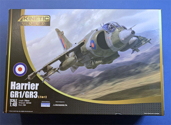
Having previously made Kinetic’s Sea Harrier FRS1 I thought it was only fitting to do its stablemate GR3 from the Falklands War when I saw that Kinetic had released this boxing. My SHAR built was not the easiest of builds (I’m still unsure whether this was my fault, the kit’s fault or I was just being overly critical of the kit). The result was that I said I had no intention of subjecting myself to another Kinetic Harrier but as the saying goes ‘time is a great healer’ and in my case it dulls the memory!! So, when this kit was released I put to one side all my previous reservations and purchased one as I just needed to do a decent GR3 and the fact that there were a lot of new tool sprues included to cover the GR3 I had high hopes that a lot of the issues I had with the SHAR would have been resolved.
I have done a quick in-box review of the kit and my initial thoughts are things look promising but that said the SHAR looked good in the box and look what happened there, but only building it will really let me see how it goes together so let’s get on with it.
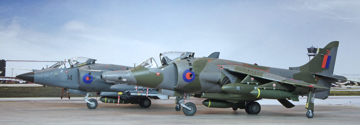
Just a quick photo of the finished model to give you an idea of the end result and a shot of the GR3 with its Sea Harrier stable mate.
First job is research and a great source of information is the Harrier SIG (IPMS (UK) Special Interest Group). The modellers on here have far more knowledge than myself and a great example is below which Nick Greenall produced to guide the modeller in the finer points of the kit.
Taken from the Harrier SIG
http://www.harriersig.org.uk
Fuselage – Some modeller’s stray from the instruction’s build sequence and do it this way:
Fit the intake/front wheel-well pieces (P25, P26) into each fuselage half.
Add the intake interior parts (N11, N12) to the outside of each half, then
Fit the intake exteriors to each half with open/closed auxiliary doors in place
N1 and N2 (open) use these for a parked Harrier on the ground, engine off.
N4 and N6 (closed) use these for a Harrier in flight at speed; not hovering or taxying!
For a Harrier in the hover or taxying, modify N1 and N2 to show all doors open.
Fit the cockpit tub in one half before joining the fuselage halves together
Finish the intakes with parts P34 and C3
Add the main undercarriage bay and airbrake bay assembly into the rear fuselage
Replace the nozzle mechanism with a 36mm (approx.) spacer fitted between the nozzle openings to keep the fuselage the correct width for adding the wings to.
Wingtips – Remove the small raised triangles ahead of the outrigger fairings inside parts 11 and I3. Adjust the shape of both parts to better fit with part I2 along the outer edge of the outrigger fairings.
Wing Leading Edge – Fill the step under the dog-tooth ahead of the inboard pylons and the step down on the fillet underneath where the wing meets the fuselage.
Wing trailing edge – Thin down the inside surfaces of the trailing edges to avoid any step down to the ailerons and flaps.
Flaps – Usually up on parked Harriers, unless the aircraft had hydraulic issues. Pilots were fined for leaving them down so causing extra work for armourers and maintainers! Often seen 8-degrees down in lower speed flight (under 180kts) to provide increased lift.
Ailerons – Usually level on parked Harriers, occasionally one up, one down. NEVER both down on any first-generation Harrier single-seater GR.1, GR.1A, GR.3, AV-8A, AV-8S or Sea Harrier; or any 1st gen twin-stick. Use aileron hinge parts E4 on both sides. (The ability to drop both ailerons was a Harrier II development i.e. the AV-8B series, GR.5/7/9 and the two seaters – TAV-8B, T.10/12.)
Tailplanes – Check with photographs to get the correct anhedral and ‘stick-forward cows get bigger’ position of tailplanes on parked Harriers. Fill the step in the port tailplane (C17) underside’s leading edge.
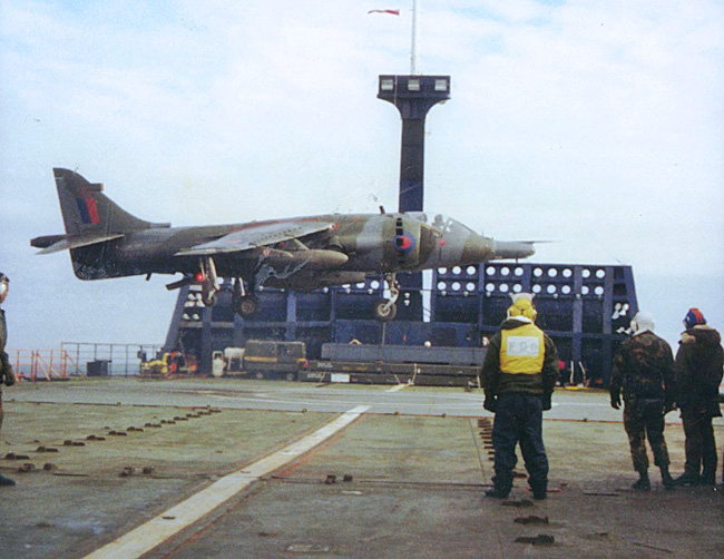
Outrigger legs – For all GR.1/GR.1As and most GR.3s use parts N18 without the tie-down rings moulded on them. For Falklands War GR.3s, including XZ997/31 in marking option 6, use the outrigger legs from sprue E, parts E28, with the tie-down rings on them. For the later XZ997/V with IV(AC) Squadron use parts N18.
Pilot’s step – Fit P39 if the model depicts a Harrier with the canopy open, engine running or not. The step was connected to the canopy by a cord – close the canopy and the step retracts.
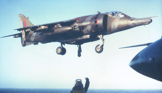
Undercarriage door and airbrake positions – Parked 1st generation Harriers front undercarriage bay doors were usually open with the twin main bay doors closed, unless they had been manually opened for inspection. The front doors could be opened/closed manually too on the ground. When the engine was running both front and main doors closed automatically to minimise foreign object damage. The airbrake is usually partially dropped on parked and taxying Harriers; see photographs.
Inboard pylons – For all GR.1/GR.1A/GR.3s use parts P27, P28, P32 and P33 with their straight leading edges. The instructions call-out the part numbers correctly, but the drawings show the Sea Harrier’s different shaped pylons (D1-D4) – do NOT use those!
Wing fences – should be fitted perpendicular to the wing leading edge, the longest sections of parts PE2 and PE3 being on the wing upper surface; ease the slots with a razor saw.
Radar Altimeter Aerials – None of the kit’s marking options need part PE24 fitted; these aerials only being fitted to some Harrier GR.3s in the late 1980s – check photographic references for the GR.3 you are depicting!
ALE-40 Chaff/Flare Dispenser – Fitted to some GR.3s which served during the Falklands War and then to many of the fleet after the war but not to XZ997! Part D28 left over from the FA.2 kit can be used if the GR.3 you build had ALE-40s; modify part I34 as needed.
Main nozzle fairing 8-fingered reinforcing plate (PE1) – This was only fitted to some GR.3s from the mid-1980s where the area had been damaged by heat and is only needed on XZ997/V in this kit.
PE Fret – This item has been expanded to include all Kinetic Harrier PE parts, so some parts are not needed for this kit, e.g. 5, 14, 15, 17, 18, 19 are two-seat Harrier parts; 22, 23 are for the AV-8S and any AV-8A with formation lights. PE25 is for US-style of radar altimeter aerial panel used on the AV-8A and AV-8S.
Ordnance – We asked for better, but the cost of new tooling is prohibitive when trying to keep the kit sensibly priced, so Raymond is leaving this to the aftermarket people. Eduard and ResKit now produce excellent UK ordnance for all Harriers and Sea Harriers, though a few gaps remain to be plugged. Note: Of the kit’s tank options, RAF Harriers only used 100-gallon tanks, they did not carry the Sea Harrier’s larger 190-gallon tanks.
Pylons – Watch Out! Discovered too late to change… The inboard pylons need their location adjusting backwards because when fitted “as made” they ‘throw’ the 100-gallon tanks 4-5mm too far forward; the tip of the tank’s nose should be level with the rear edge of the small fuel vent E10 when it’s in place. The inboard pylons are also 4mm too long, this needs to be removed from their trailing edges. The outboard pylons need moving 3mm outboard and also need moving back about 2mm. Adjust all pylons’ upper surfaces so they do not carry their stores nose down.
Time for some fettling…
Looking forward to seeing some fantastic Harrier GR.1 and GR.3 builds on the forums and on the tables at shows in 2021.All the best
Nick Greenall
