Wheel bays, wings and engine nacelles
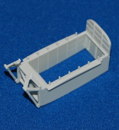
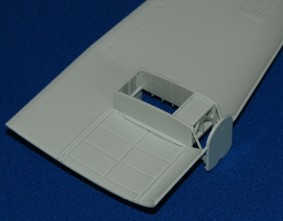
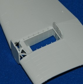
The wheel bay assemblies are straightforward and a good fit, all parts needed to go into each wing just clicking into place. There’s some nice detail in there that should look good on the finished model.
Remember to drill out the holes indicated in the instructions for the six fuel jettison pipes (3 under each wing), plus the small holes for the small parts above and around each engine nacelle.
The wings can now be joined and glued. Again, they’re a very good fit, although the training inner wing edges have two surfaces that don’t mate perfectly square. No great shakes, with some tape to bind it all together and plenty of liquid poly cement.
The wing assemblies are then set aside to dry.
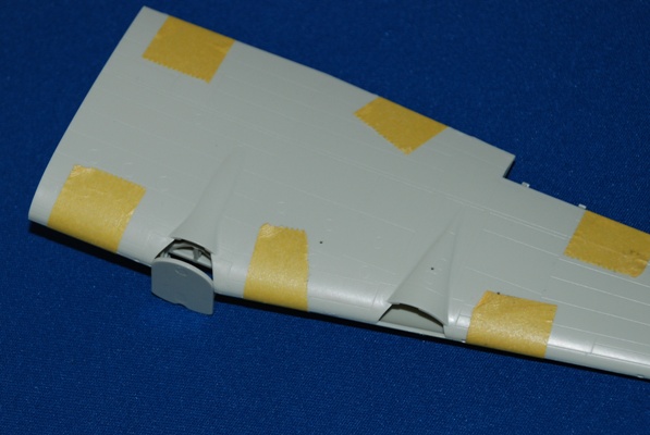
The engine nacelles are an excellent fit to the wing following some dry test-fitting – both inner and outboard nacelles.
You do need to decide at this point what intake arrangement you are going to need for the aircraft that you intend building. Revell have done well including all three options applicable to various Merlin engine arrangements. From reading around the references, it seems that all three types were widely used and, for my specific aircraft, I need Parts 161 and 162 for the intakes.
These fit extremely well and already I can see that only a little sanding will be needed to make good the joins.
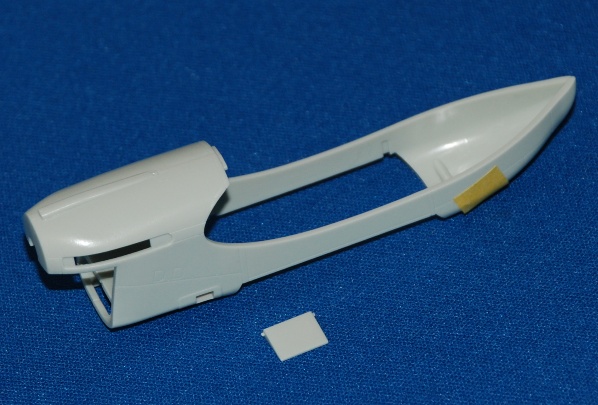
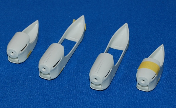
I have left the nacelles to dry thoroughly and will sand and prep them ahead of attaching to the wings later. So, onto the ailerons…
Oh Dear…
Stages 41-42 see you adding the outboard ailerons to the wing sections, which leads us to a serious problem.
Revell have decided to make these parts movable; all a bit gimmicky really and, more significantly, they seem to have moulded the ailerons incorrectly with a large gap all along the front leading edge. What’s that all about?
I have now trawled through dozens and dozens of images of Halifax aircraft – Mk.II’s and III’s and nowhere can I find a single one where the huge gap that exists on the Revell wing is evident. This seems bizarre, as the fit of the parts is so good. I kept thinking I had made a c—k up here, but I don’t think it’s me this time.
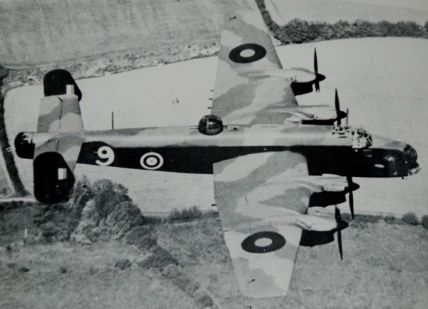
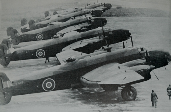
I have included the two images above to show you the aileron from an aerial view. See what I mean? No gap at all on the front edge of the outboard ailerons.
Out with the Milliput!
The Gallery above shows the problem up close. So, to begin to rectify it, I masked off the trenches and filled them with thin rolls of Milliput.
This two-part filler is excellent and using water the excess is smoothed into the hole and excess removed with the edge of a steel rule. The masking tape you can see here is used to protect the surrounding area and doing this means that there will be minimal sanding tomorrow when I come back to it.


