Sub Assemblies
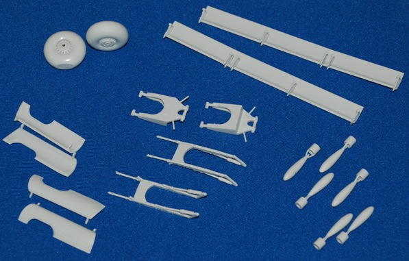
You can see above that I have brought together most of the sub assemblies completed so far; these are largely going to be set aside for spraying with the main components as appropriate.
More issues! The bomb bay doors…
As you can see I have gone on merrily assembling everything so far and, to be honest, this has been a very enjoyable project.
Despite the ‘issues’ so far, there has been a pretty simple fix, mainly because I happened to have a Revell Lancaster kit to hand; had I not, the experience may well have been quite different.
You can see in the image of the sub-assemblies above that the bomb bay doors are assembled and ready to be attached. Hold on…all is not what it may appear! I took a closer look at these images from the references quoted at the start…
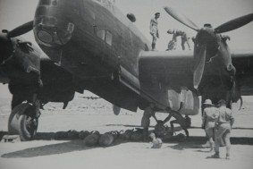
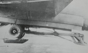
The bomb bay doors in fact comprise a double set of doors on each side; an inner set and an outer set. The inner doors appear to slide down and form the flat under belly of the aircraft, while the outer doors set higher up the fuselage side are canted out when open, and shut clam-like when closed.
You can see the problem? Only the inner doors have been supplied!
Revell, by default, leaving the builder to accept the outer pair of doors as moulded in with the side fuselage half and marked only with a two-dimensional panel line. Sorry, this isn’t acceptable (to me at least) and you are left to ponder a solution!
Inner bomb bay doors first…
First the good news: You can use the doors as supplied to pretty much locate as suggested. The hinges are good and everything lines up well.
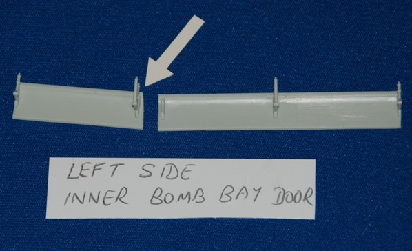
You do need to split each one at the ‘break’ line where the rear portion of each inner door changes angle slightly and deflects upwards. A scalpel will ensure a quick separation of the longer front section and shorter rear portion.
Take a bit off the front edge of rear door where you see the arrow pointing and this will enable you to preserve the slight angle change in the door’s profile when fitted.
Repeat for the opposite side.
New outer bomb bay doors…
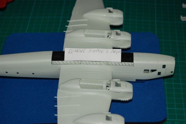
You can see in this image the area that needs to be removed from the side of the fuselage.
Obviously, had I looked at or noticed this problem at the start of the build I would have removed the shaded area while the fuselage halves were separate. Further good news though is that the shaded area can be easily removed even at this late stage.
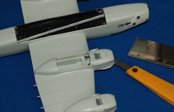
The recessed panel line along the edge of the shaded area acts as a great groove along, which you can draw your Olfa P-Cutter and, after about a dozen firm but not hard passes, the shaded area begins to separate.
I used my razor saw to make the fine vertical cuts at the front and aft ends of the bomb bay door. This was much easier and quicker than I thought it was going to be. Keep the sections you’ve just removed from each side, as they will be useful for measuring the new outer bomb bay doors that we are going to make shortly.
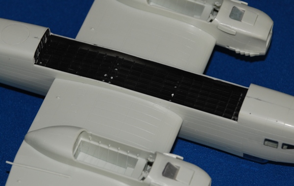
In go the inner bomb bay doors…
It is safe to now add the inner bomb bay doors, using the location holes provided.
I did need to do a bit of jiggling to get the most acceptable fit, but everything did eventually line up ok. It’s a good idea to use cyano glue here for added strength, as we are going to fabricate new outer bomb bay doors using metal foil.
New metal outer bomb bay doors…
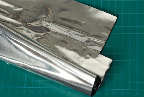
I knew this would come in handy one day! What I’m on about is this sheet of metal foil I picked up from a stand at the Model Engineer Exhibition some years ago. It’s not as soft as lead, but not as firm as brass and, not having any brass sheet (by preference) that is thin enough to use, it’s out with the metal foil to get started.
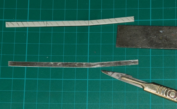
Using a section of the fuselage removed earlier, you can use this as a rough template for the new outer bomb bay doors. The section will need to be deeper (higher) though, extending down from the fuselage bomb bay door hinge line to about 1.5mm from the edge of the inner bomb bay door edge.
Look at the pics of the real bomb bay doors included here and you’ll get the idea.
When you’re happy that you have two sections of the correct length and height (depth) we come to the tricky part, creating the curved lower edge that is very distinctive on the outer Halifax bomb bay doors.
Rolling, rolling, rolling…
So the song goes and that’s what we are going to do here. I am producing a short HD video as we speak that demonstrates the technique being applied here, so watch out for your TB for that (a link will also be provided here as soon as it’s uploaded).
The key thing is to find two straight rods (wood or brass will do) that won’t flex under firm pressure. For this task I took a thin brass rod that’s about 1mm diameter and another about 3mm diameter.
There are going to be two rolls for each outer bomb bay door – one for the front (longer) section of the door and one the rear.
Taking the front section first, I placed the smaller rod under and along the front lip/edge of the metal foil; the larger rod is placed on top of the foil all along the bottom edge. This can be tricky, but after a couple of practice attempts I managed to hold everything in place and all square.
Next, gently begin to slide (roll) the bottom rod along with the smaller rod beneath a few millimetres and you see the curve begin to develop. Just stop when it looks right.
Any unwanted deformation of the flat areas of the foil can be removed by gently swiping a flat surface across the affected area(s). Then, just repeat this process for each of the remaining section of the outer doors.
In the short Gallery Grid below, you’ll see a small gouge on the left fuselage side just in front of the bomb bay doors where I slipped using the Olfa P-Cutter. This has been filled with cyano, sanded and smoothed back to restore the surface.
Phew! Well, that’s it for this update. Plenty to be getting on with here!


