1 | 2 | 3 | 4 | 5 | 6 | 7 | 8 | 9 | 10 | 11 | 12
Review by Julian Seddon
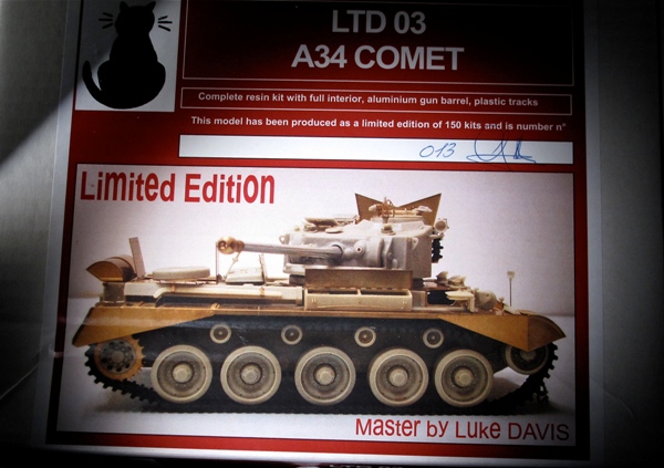

A short history of this vehicle is written up in my Here Now review of Resicast’s fantastic Comet. I shall now have to try and live up to its craftsmanship during construction and endeavour not to make a sow’s ear of these beautiful mouldings!
The Resicast Comet is produced in resin only with six brass sheets of varying sizes. I have not counted up the parts but there must be 5-600 + bits to stick together. All that into a 1:35th scale model!! You will need a decent set of tweezers and Model Craft’s pick and Place tool.
The instructions are on a CD. I mentioned in the Here Now review that it will be necessary to read them very carefully and try to dry fit as far as possible ahead as things will become very crowded in the interior as construction proceeds. If you print out all the sheets there are 157 of them! They have quite a bit of reference material in them and in addition there are photos of all the various stages during and after assembly. They are very clear.
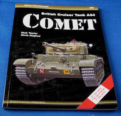 In addition to the reference in the instructions there is quite a lot on the internet on the Comet, particularly exterior shots of the different examples on view in museums. I have also purchased The Taylor Hughes book on the subject.
There is a lot of good material in this book both exterior and the crew interior. However there is nothing on the engine or the engine compartment. And I am finding it very difficult to find any photographic reference for this anywhere. There are, not surprisingly, almost no shots of the exposed suspension. This is concealed behind a body plate on the real thing and to get at it I guess one has to remove the whole thing. I have no idea what colour it was painted but I will take a guess that it was some sort of protective coat.
 The Hull…
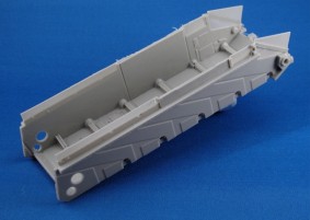
If you recall the hull is in one piece and includes some interior detail and footplates for the parts that adhere directly onto it.
The instructions say that all the internal bulkheads should be installed before proceeding any further. Two of the bulkheads have ribs running down them. These are brass and have to be bent at the edges to form a “U”. The edges are very narrow and the brass is quite sturdy.
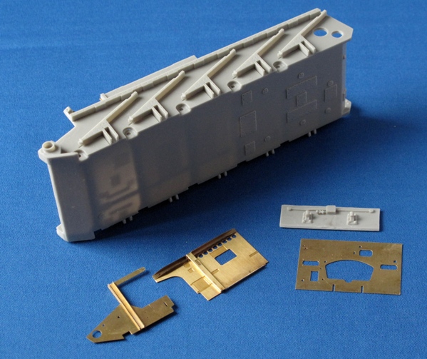
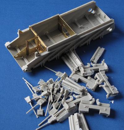 I annealed the pieces (applied flame directly onto the brass piece, this makes it more pliable – check out your Techniques Bank) also I scribed the bend line after finding that annealing alone was not enough. The process worked and I will adopt that as a practise for this construction. In the photo above I have already installed the 10 suspension mounting brackets. The above photo shows the bulkheads lined up (not glued as yet) in the slots provided in the hull. The fit was very good and only need the smallest of adjustment to slot in perfectly. Lined up at the bottom of the picture are some of the next pieces that make up the suspension. Each one is on a mounting block – they are however pretty easy to remove and so far there have been no breakages doing this.