The Intakes
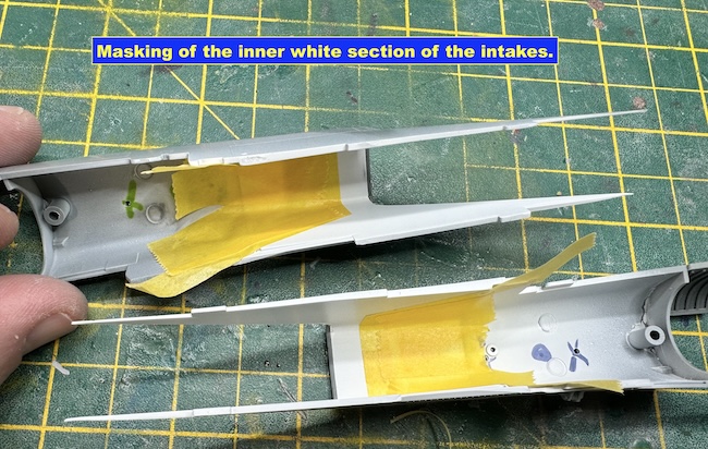
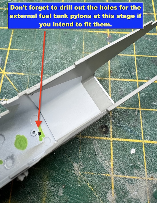
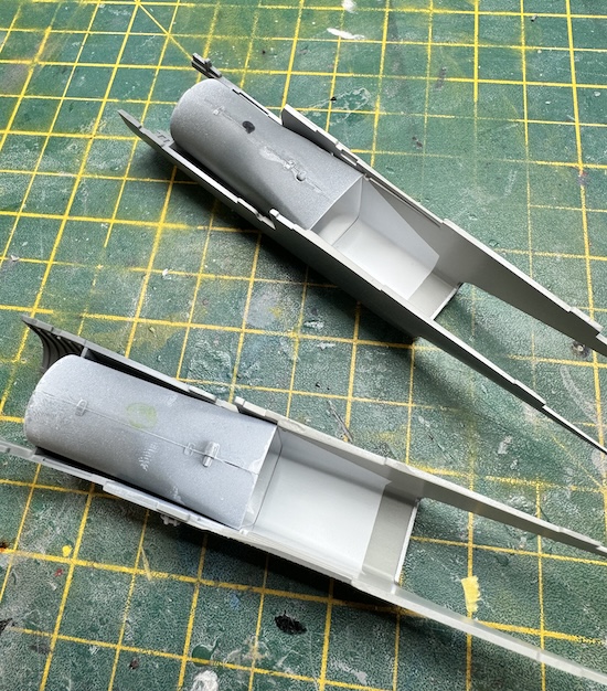
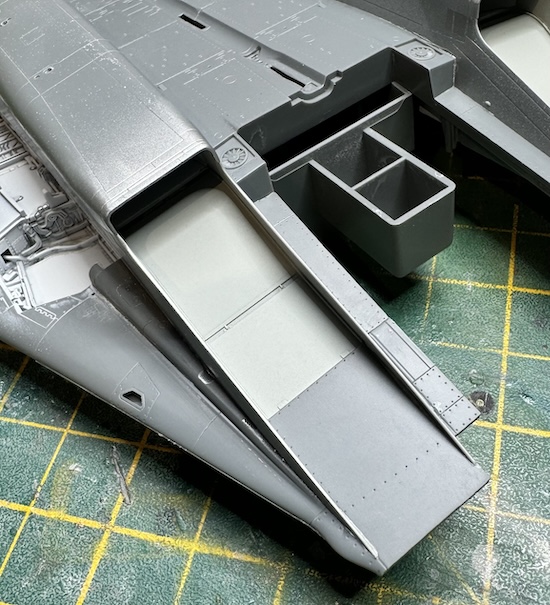
The first stage of the intakes is to paint up the inner demarcation between the outer grey and inner white. This is best done as shown in the picture. Also, don’t forget to drill out the holes for the external fuel tank pylons if you intend to fit them.
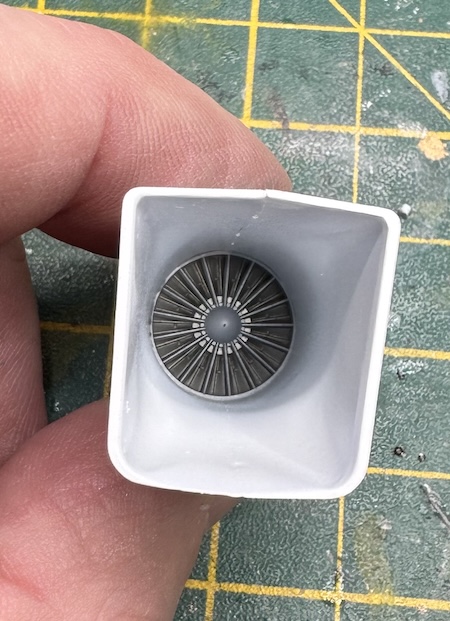
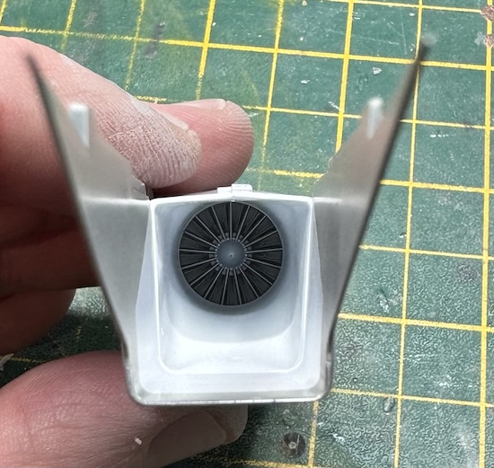
The compressor blades are nicely moulded when fitted into the inner intake sections. This can then be fitted into the outer intake. Care needs to be taken here to eliminate any visible seams. A top tip to minimise the visibility of these seams is to have the intake ramps in the lowered position as these will block a lot of the view up the intakes – the ramps will naturally drop into this position over time as hydraulic pressure is lost in an unpowered aircraft.
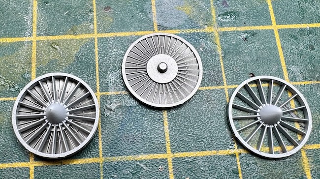
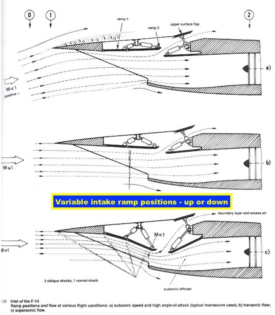
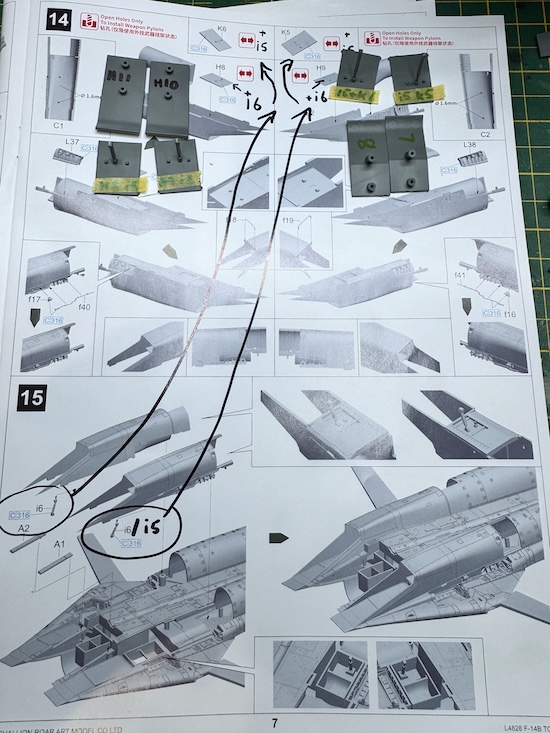
As said above the intakes on an F-14 have ramps on the upper surface that move up and down depending upon the speed of the aircraft in order to control the speed of the air entering the engine. The Tamiya kit has these fixed in the upper position but both the AMK and this kit have the options to fix the ramps in the upper or lower positions. When assembling this stage of the model be careful of the part numbers as they are incorrect in the instructions – the picture shows the corrected part numbers.
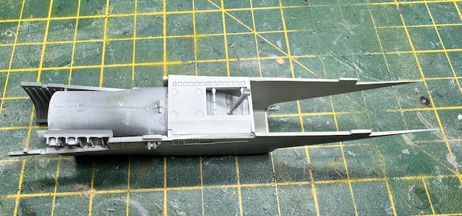
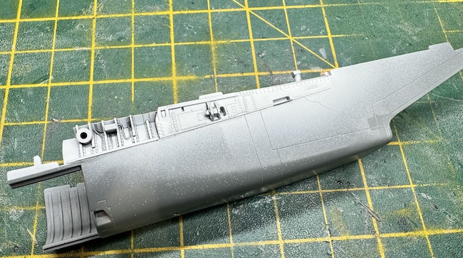
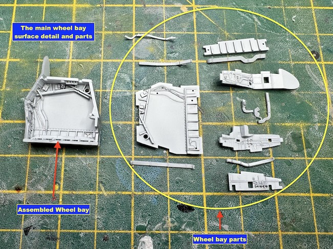
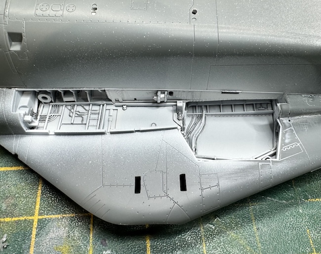
The main wheel bays
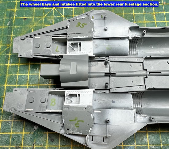
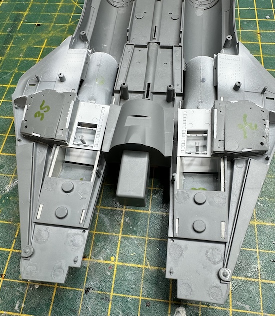
As with the nose wheel bay the main wheel bays have great detail in them, the best of all the F-14 kit I have built. I really don’t see the need for aftermarket wheel bays for this kit they are that good.
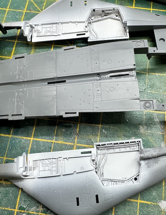
The intakes and wheel bays can then be fitted into the lower rear fuselage. There is a lot to fit together at this stage so care needs to be taken but if you take your time and dry fit to ensure everything is good everything should go together as advertised – mine did as shown in the pictures.
Paul Ainsworth says
Hello,Dave – A magnificent build of the Tomcat.

One to be very proud of indeed.
May I ask how the GWH kit compares to the Tamiya kit as far as detail and ease of construction are concerned?
Best Regards,
Paul.
Daniel Beeden says
Fantastic build and a beautiful paint scheme. Great work