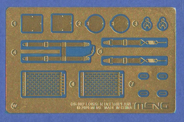
There is an etched fret supplied with the kit which has cooling jackets for the machine guns, seat belts, two types of inspection panels for the front fuselage (these are also supplied as plastic parts) and cable outlet points for the rear fuselage.
I have yet to use the brass parts, but suspect that annealing them by heating and then dipping them immediately into cold water will be helpful. This should soften the metal and make it easier to get the seat belts to conform to the shape of the seat and to get the perforated gun cooling jackets bent to shape.
I must admit, that while guns with etched cooling jackets look far superior to a solid injection moulded item, I’m not looking forward to trying to bend them to shape. My attempts at shaping gun cooling jackets always end up with them having a pear-shaped cross section rather than the perfectly circular section that seems to be quite easily obtained by every other modeller on the planet!
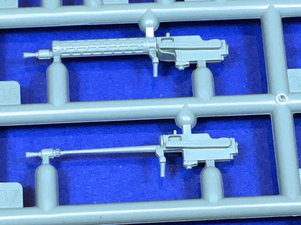
Thankfully, just in case my attempts go literally pear-shaped, there are two sets of guns included in the kit, one moulded in solid plastic and one with just the barrel to allow the brass parts to be fitted.
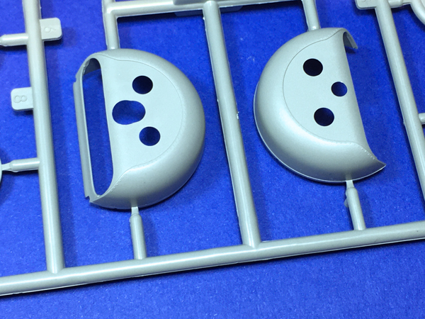
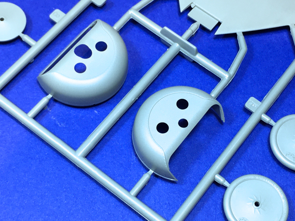
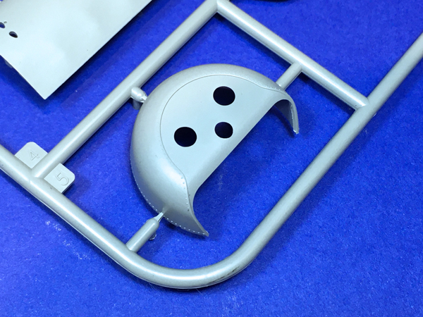
This kit offers three different styles of cowling. Note that there were other styles used on the Fokker Dr.1 with some having enlarged cooling openings etc, so it would be worthwhile to check references if deviating from the marking options in the kit.
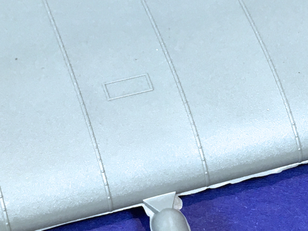
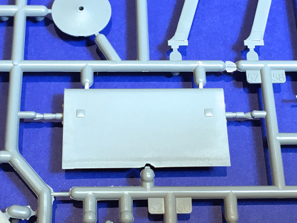
There is an inspection panel on the top surface of the upper wing which is represented by a small oblong raised area on the kit.
I think that the inspection panel on the Dr.1 would have been either directly on top of the wing spar or perhaps just behind it. There were a number of accidents involving wing failure on the aircraft so perhaps it was felt that it was necessary to be able to check the wing spar?
This arrangement would probably have made a clear panel and any underlying structure very difficult to mould. I’m not sure how best to represent this panel, on the model. Perhaps painting the area brown to represent the underlying wooden wing spar and then gloss varnishing would work.
I think that this panel was not present on the Fokker F.1 (again worth checking reference material). If this is the case it would be very easy to sand away the raised detail.
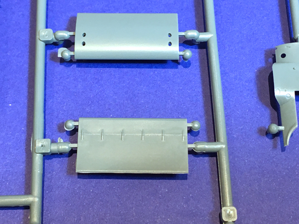
The kit provides two sets of ailerons one is for the Fokker F.1.
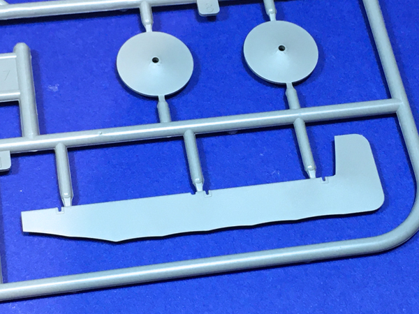
The other with a slightly different shape and larger surface area is for the Fokker Dr.1.
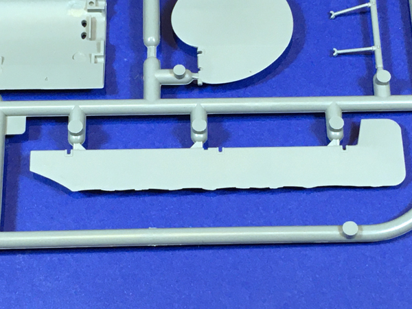
Note that while the trailing edges of the flying surfaces on the rest of the kit are very neat, there is some flash to clean up on the ailerons for the Fokker Dr.1.
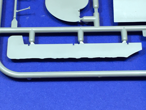
The Fokker F.1 had a slightly different elevator profile from that on the Dr.1 with a rounded leading edge while that on the Dr.1 was straight. Both types are provided in the kit.
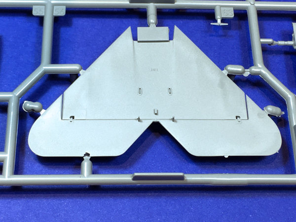
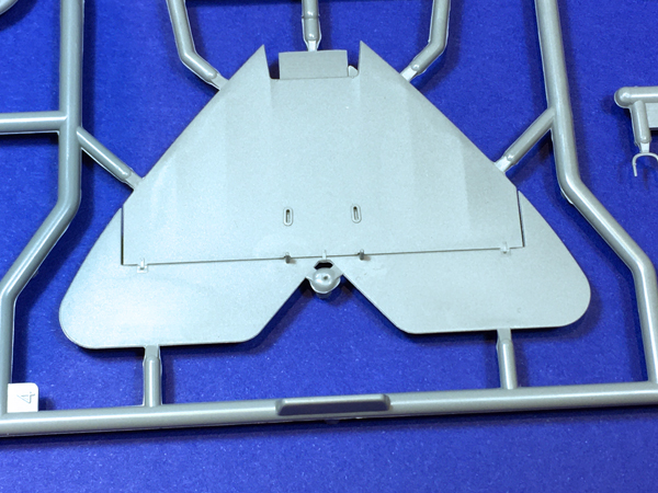
The Fokker Dr.1 was technically speaking a triplane. However, there was another lifting surface between the wheels. The underside of this part looks different from the plans for the Fokker Dr.1 shown in the Windsock Datafile Special on the aircraft. These plans show a joint across the underside of this fairing about 1/3 of the way from the front that is not present on the Meng kit. I cannot show these plans here for copyright reasons, but this feature along with some other details that are not present on the Meng kit can be seen on the underside of the fairing in the excellent Eduard 1:48 scale kit shown below.
I’m not sure which of these kits is correct and I suppose that someone has to be wrong so perhaps some more reference checking would be a good idea here. The detail on the Eduard kit can be compared with the same rather featureless part in the Meng kit shown below.
Note that this was one of the parts helpfully pre-broken in my kit, but a fix with some filler should not be too difficult.
Ask a question or add feedback:
You must be logged in to post a comment.