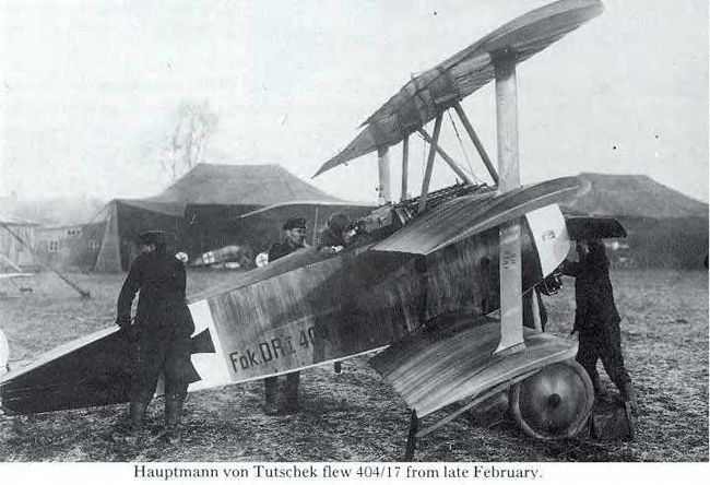
Period photos show that the covers over the spokes on the wheels of these aircraft were lighter in the centres than they were on the outsides next to the tyres. The Windsock publication on the Fokker suggests that this was because they were painted using one stroke of a brush while the wheel was spinning so that the brush had less paint on it by the time the painter reached the centre of the wheel.
This feature can be seen on a photo of a Dr.1 that I found on the internet. This may not have been common to all Dr.1s, and the wheel covers were often over painted in squadron colours. However, the depiction of a solid colour in Meng’s instructions is perhaps worth checking. Out come the reference books again!

The instructions also do not mention how to paint the upper part of the lifting surface between the wheels. I believe that this was often painted in solid olive green rather than having the streaked camouflage applied to the rest of the aircraft and that this colour sometimes wrapped around to the joint on the underside.
One thing that is definitely lacking from the instructions is a rigging diagram. While the Dr.1 had few rigging and control cables compared with other aircraft, there are definitely a few that need to be included.
These are – from front to back:-
· Bracing wires between the front pair of centre section struts.
· Bracing wires between the front pair of undercarriage struts.
· Aileron control cables on the upper and lower surfaces of the upper wing running from inside the wing to the control horn on each aileron.
· Paired aileron control cables crossing each other inside the cockpit in front of the pilot. These emerged from the holes in the cockpit coaming and ran into the lower surface of the upper wing.
· Six control cables that ran from the control column and rudder bar under the pilots seat, through the plate in the fabric panel behind the pilot, emerging at the rear of the fuselage to the control horns on the rudder and elevators.
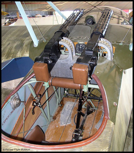
· Bracing wires between the upper and lower structural members of the fuselage. These would probably be visible through the cockpit opening as shown in the photo of a restored / replica Dr.1 below.

There were some cards in the kit with some information about the Dr.1 and Manfred Von Richthofen in three languages (with a somewhat odd English translation from what I assume to be the original Chinese). I thought these were a bit of a gimmick and that they would not be of much use to anyone whilst a proper rigging diagram definitely would have been!
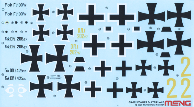
There are markings included for four aircraft and these are:-
· An overall red Dr.1 flown by Manfred Von Richthofen. This has the earlier iron cross markings which were later changed to straight sided crosses shortly before he was killed.
· Verner Voss’ F.1. This shows the streaked camouflage applied over a turquoise base colour rather than the clear doped linen of the Dr.1. It also lacks the ‘wrap around’ turquoise strip along the bottom of the fuselage sides and around the edges of the horizontal tail surfaces that were present on the Dr.1.
· A Dr.1 flown by Herman Goering with the rear of the fuselage and horizontal tail surfaces overpainted in white.
· A camouflaged Dr.1 flown by Walter Göttsch with black and yellow horizontal tail surfaces and non-standard yellow identification numbers on the rear of the fuselage.
The transfer sheet is well printed though the transfers look quite thick with prominent carrier film. How they work in practice remains to be seen.
There are a few items which I think could have been included on the transfer sheet. These include the thin black datum line running along the fuselage behind the cowling, the Axial logos for the propeller blades and the text that can be seen on the wing ties in some period photos.

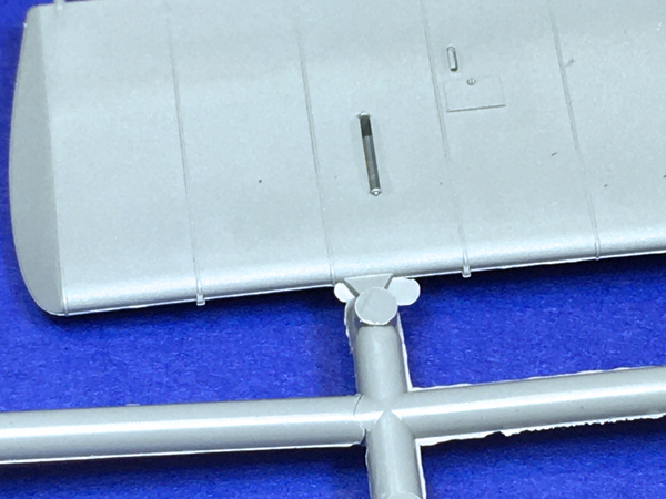
The Dr.1 had two stacking points on the leading edges of each of its wings – though it seems these were not always present. These are represented by little pips on the kit’s wings, but the kit has four stacking points on each wing instead of the two that actually existed.
The position of these stacking points seems to have varied between aircraft. Some had them inboard of the wing ties, some outboard and some in line with the wing ties. I assume that removing the unwanted stacking points from each wing, depending on the aircraft being modelled, was something that Wingnut might have put in the instructions, but Meng did not?
I don’t see these tiny items surviving the clean-up of the wing leading edges and they will probably need to be replaced, perhaps with plastic or brass rod.
Again, references will be useful here.

Ask a question or add feedback:
You must be logged in to post a comment.